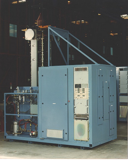
Line type modulators are typically developed for driving klystrons, high power RF tubes, and other high voltage loads that require tight pulse shape control (usually a square pulse with minimal rise/fall times and minimal flat-top ripple).
Line type modulator technologies:
Example Projects:
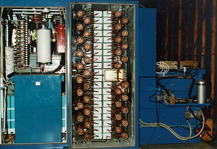
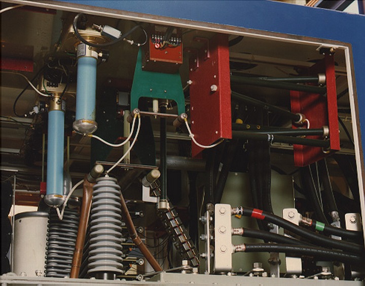
520 MW Klystron Line Type Modulator Technical Specifications
- Output voltage: -200 to -600 kV
- Output current: 870 A @ -600 kV
- Flat top pulse width: 10
520 MW Klystron Line Type Modulator Technical Features
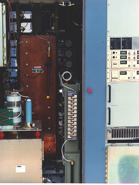
- "Rough" voltage regulation and control
- Limits input power line harmonics
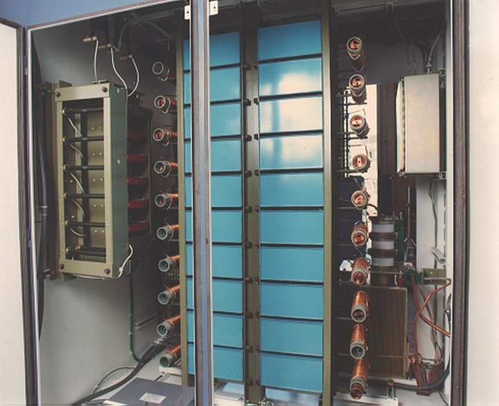
- Each 10 ohm, 20 sections
- Air insulated to 75 kV
- Tunable inductors provide output pulse shaping for low ripple flat top


Photos of the power supply system may be seen on the
Ness Engineering SCR Phase Control Power Supply Experience page.More detailed photos of the solid state, command charging switch assembly and resonant charging system can be seen on the
Ness Engineering Solid State Switching Experience page.
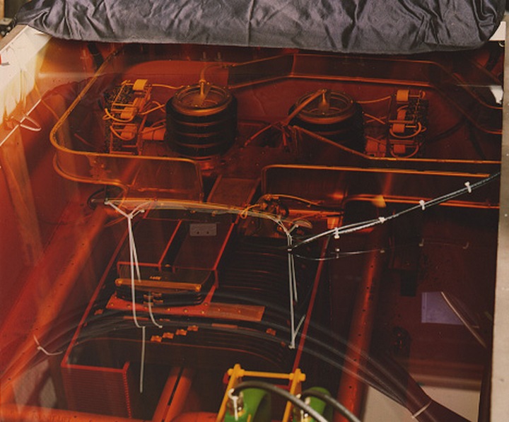
46 MW Klystron Line Type Modulator Technical Specifications
- Output voltage: -230 kV
- Output current: 200 A
- Flat top pulse width: 60
46 MW Klystron Line Type Line Type Modulators Technical Features
- Coupled cavity linac (CCL) portion of Superconducting Super Collider (SSC)
- Eleven 46 MW klystron modulators required
- Thomson CSF TH-2143 klystron
- Five Maxwell CCDS capacitor charging power supplies operate in parallel
- Each power supply rated 35 kV, 8 kJ/s
- Charge Pulse Forming Network directly to highly regulated voltage without resonant charging and de-qing
- Diode isolation / protection circuits to allow continued operation if one unit fails
- 20 Section Rayleigh PFN
- Air insulated and charged to 35 kV
- Tunable inductors provides pulse shaping for low ripple (less than +/-0.25%) output pulse
- ITT F-331 thyratron generates long (60-75

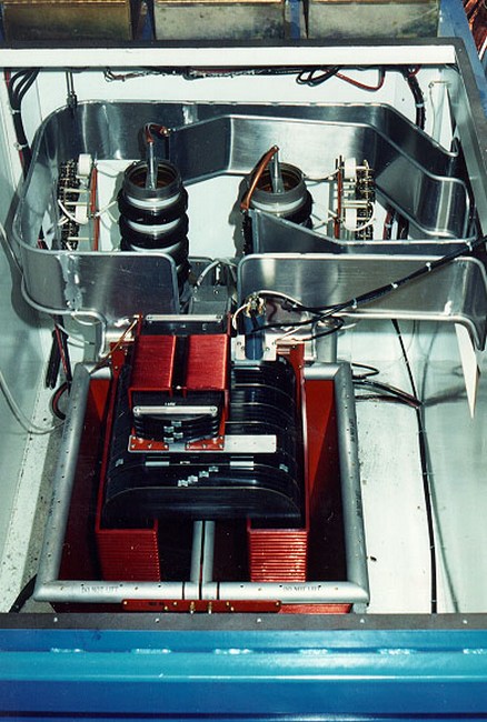
8 MW Klystron Line Type Modulator Technical Specifications
- Output voltage: -125 kV
- Output current: 64 A
- Flat top pulse width: 90
8 MW Klystron Line Type Modulators Technical Features
- Drift tube linac (DTL) portion of Superconducting Super Collider (SSC)
- Five 8 MW klystron modulators required
- Thomson CSF TH-2140 klystron
- Two Maxwell CCDS capacitor charging power supplies operate in parallel
- Each power supply rated 35 kV, 8 kJ/s
- Charge Pulse Forming Network directly to highly regulated voltage without resonant charging and de-qing
- Diode isolation / protection circuits to allow continued operation if one unit fails
- 20 Section Rayleigh PFN
- Air insulated and charged to 35 kV
- Tunable inductors provides pulse shaping for low ripple (less than +/-0.25%) output pulse
- ITT F-307 thyratron generates long (90-105
Send consulting inquiries, comments, and suggestions to
nessengr@san.rr.com [HOME] [RESUME] [PUBLICATIONS] [NEWS] [LINKS] [CAPABILITIES] [TECHDATA]Ness Engineering, Inc.
P.O. Box 261501
San Diego, CA 92196
(858) 566-2372
(858) 240-2299 FAX
© Richard M. Ness and Ness Engineering, Inc. |
Website File Auto-Update Javascript courtesy of www.javafile.com Download the Script